Welcome to class number 13, which deals with removing and replacing an overpass. This is a continuation from class number 12, which showed the initial construction activities which were terminated early. This is the follow-on contract, which completed the construction of the bridge.
You will recall that there was ample space here to shift all of the traffic to one side while the other side was removed and replaced. That's the traditional approach and, eventually, that's what was done here. It was determined that the bridge here was too long, and the span could be shortened. That presented the opportunity to build the new abutments inboard of the existing abutments. That construction could be completed without any interference to the public.
Only after the abutments were built as far as they could be built, then and only then, would the traffic be shifted and half the bridge would be removed. It was an innovative approach, but it seemed to contribute to some problems. The north abutment was built as far as it could be built. That went along very smoothly, but when activity shifted to the south abutment and the location of the South abutment is pretty much where the auger is parked.
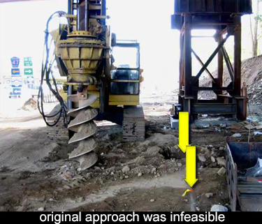 You can see it's very close to the temporary tower and it requires an excavation at least 10 feet deep. The sheeting that was called for here was soldier piles and lagging. The auger has begun pre-drilling for the soldier piles. The line of sheeting passes very close to and, in fact, passes slightly underneath the existing tower. Soldier piles and lagging cannot accommodate a concentrated load like that. I'm not sure there's any supportive excavation technique that could accommodate that kind of concentrated load.
When this became apparent, construction activity stopped and eventually the contract was terminated. There may have been more issues, which I'm not aware of, which contributed to the early termination of the contract, but this seemed to be one of the triggers.
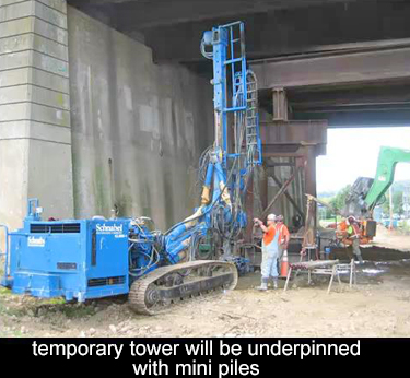 When construction finally resumed with a new contractor, the very first activity were installing drilled piles to re-support the existing tower. The name on the drill rig here is Schnabel, and he is a foundation contractor. I wanted to give recognition to his name, because he both designed and installed the support of excavation system. They did not use soldier piles and lagging. That would have been very difficult to install underneath the existing structure. The method they used is somewhat unusual, but it seemed perfectly suited to the situation that was present here.
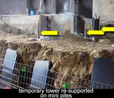 Here, the drilled in piles have been installed and they are attached to the existing footing by means of a bracket. The footing is now being carried by six drilled piles and those piles reach an elevation far below the excavation required for the new abutment. That tower has now been underpinned and is perfectly safe for the excavation to begin -and it has started here.
The system used here will be soil nails and shotcrete. You can see some of the elements in this photo. There's a filter fabric that will be behind the shotcrete in order to prevent any accumulation of water. I also want to point out that the line of excavation is now several feet away from the existing foundation.
The soldier piles and lagging, the way they were laid out, they would be right alongside the face of that temporary footing. The shotcrete is being installed right at the neat line of the permanent footing. You could have done that with the soldier piles and lagging also, but that still would not have made that temporary tower safe. However, it was done here with the shotcrete application, and the new abutment footing will be poured hard up against the shotcrete.
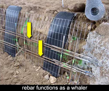 Here, you can see the fabric is also a layer of rolled out mesh, which will reinforce the shotcrete. And there is some rebar in a pattern which resembles a whaler, so that the loads can be carried by the soil nails. These dowels are not the soil nails, but they are markers to indicate the location of the soil nail. Once you shotcrete this, all of these elements would be hidden.
continue >