This is a three span continuous bridge. Here, you can see the Ironworkers splicing two sections together on the ground. In order to make this splice, the girder must be supported in a no load condition. That is to say, all of the dead load camber has to be taken out. You can see these supports have been placed to a predetermined elevation, so that the dead load deflection is removed. These members were originally assembled in the shop, also in a no load condition. In that unloaded condition, with no dead load deflection, that's when the splice material was drilled. That condition of no dead load deflection has to be reproduced here at the job site, before the connecting material can be reinstalled.
Here, two Ironworkers are installing the high strength bolts, which make up this connection. The Ironworker standing behind the girder is using an impact wrench. From time to time, these bolts should be checked with a calibrated torque wrench to make sure you're achieving the correct torque.
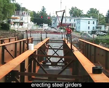 Here, two Ironworkers are installing the intermediate diaphragms. They are wearing harnesses, and they are tied off to prevent an accidental fall. I'm a little concerned about the iron worker on the left, who is actually leaning on his harness and his safety line is taut. He is depending on that for his support. I don't think that’s the best practice. They could easily have put some timber planks down between the bottom flanges of the girders, and that would have been their primary support. The fall protection is their backup for an emergency. I don't think it's good practice to use that as your primary support.
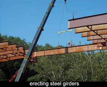
The ironworker on the right has waited until the diaphragm is pinned in place. Now, he's come down and he can stand on it. His lifeline is slack. I think that is the better way to do this. Here, the last member of that continuous girder is being installed and a spreader bar is being used, instead of picking the girder at the midpoint, that load is being distributed in an attempt to also minimize the dead load deflection of that member.
 Now, in the field, if you're trying to fit a piece of steel like this in between two previously erected pieces of steel, the chances of getting those holes aligned are very, very small. Typically, the base plate supporting the steel are not fully-welded in their final position. There is an opportunity to have some movement there in order to align these holes and join these pieces. Only after they are joined, should that supporting base plate be welded in place.
Here is a detail of the installation of the sheer connectors. This round shape is a ceramic ferrule. The ironworker inserts the stud with a sheer connector, inside the ferrule, brings it to the location where he wants to install it. When he squeezes the trigger, an arc is generated. That melts the surfaces and automatically plunges the stud into that molten pool, which is held in place by this ceramic ferrule. Afterwards, you need to break away the ferrule and dispose of it. That should be removed before you place the concrete. Now, there are many other hardware devices which take advantage of this technology and allow you to install them very, very quickly and effectively.
After the metal pans are installed, you install the sheer connectors. The inspector is striking each one to make sure there's a good connection. What I've also seen is a few connectors are actually bent over and right angles, which seems like a much more demanding test. She's getting very close to the iron worker who's installing the studs, and he's very unhappy about this - chases her away.
After the steel is erected, a survey is made of the actual elevation of the steel over its full length, and that is compared to the theoretical elevation. You need to account for the dead load deflection, which will take place when the concrete is placed. You finally come up with a number and it's written right down here as .062, which is about three quarters of an inch. This tells the installer that the formwork should be set three quarters of an inch higher than this reference point. That will put the underside of the deck at exactly the right elevation. After the dead load takes place, the concrete will be in its final theoretical elevation.
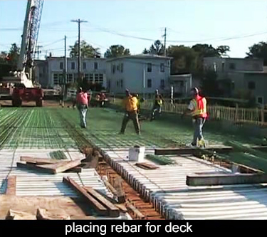 I wanted to show you the activity of placing the rebar for the deck. In the foreground, these white strips have been placed in the depressions of the corrugated metal form. They are strips of Styrofoam. If you did not install those strips, you would be wasting a lot of concrete, filling the depressions. At the same time that would simply be adding to the dead load on the bridge. Those spaces are filled out with Styrofoam.
Here, the ironworkers are shanking out the steel. Everything here has to be done by hand. All the bars have to be carried to their locations and then wired in place. They are placing the transverse bars for the top mat of steel, and the bars are supported on chairs. In this case, they are continuous chairs, which will set them at the correct elevation.